PCIe Bifurcation – What is it? How to enable? Optimal Configurations and use cases for NVMe SDDs/GPUs
One of my colleagues asked me about “Bifurcation” when it came in a discussion about running multiple NVMe drives from a single PCIe slot. As I explained “what it is” and why one should consider it before making a motherboard purchase, I shared my own home lab experience – which brought me to write this blog for the wider community.
Background: I had multiple disks in my Supermicro server – three(3) NVMe SSD, two(2) SSDs and two(2) HDDs. One of my SATA HDDs (2TB in size) decided to go kaput recently. I thought of replacing it with an equivalent size internal SATA SDDs to keep the expense low. Checking pricing on Amazon, 2TB SSDs were somewhere in the range of £168 to £200 and somehow I stumbled upon the WD Blue SN550 NVMe SSD 1TB for just £95 – I remember when I bought my first Samsung EVO 960 1Tb NVMe for about £435 in September 2017 and the same brand/model for 2TBs were around a grand!
The read and write speed of 545 MB/s and 540 MB/s respectively, of the fastest 2TB SATA SSD i.e. SanDisk SSD Plus (in the price bracket mentioned above) was no comparison to the WD Blue SN550 NVMe SSD’s 2400 MB/s and 1950 MB/s respectively. As I was already using 3 NVMe SSDs, I loved my nested VMware vSphere (ESXi) home lab run “smooth as butter”, it became a no brainer for me to consider buying two(2) x 1TBs WD NVMe SSD instead. Of course, I would have to invest additional money to buy more NVMe PCIe adapters, but I would rather spend a little more money now for future proofing my home lab/server along with the additional speedbump ;).
The PCIe based peripherals in my home lab are Supermicro Quad Port NIC card, Nvidia GPU and Samsung NVMe SSDs. This blog will focus on NVMe SSDs and the GPU as an example, covering the following:
- What is PCIe Bifurcation?
- Interpretation of an example motherboard layout and its architecture
- Limitations of the example motherboard
- Understand default PCIe slot behaviour with Dual NVMe PCIe adapter
- How to enable PCIe Bifurcation?
- Optimal PCIe Bifurcation configurations – three(3) use cases
Before we begin, let’s get the dictionary definition out of the way:

What is PCIe Bifurcation?
PCIe bifurcation is no different to the definition i.e. dividing the PCIe slot in smaller chunks/branches. Example, a PCIe x8 card slot could be bifurcated into two(2) x4 chunks or a PCIe x16 into four(4) x4 i.e. x4x4x4x4 OR two(2) x8 i.e. x8x8 OR one(1) x8 and two(2) x4 i.e. x8x4x4 / x4x4x8 (if it does not make sense now, it will later – keep reading )
Note: PCIe Bifurcation does not decrease speed but only splits/bifurcate lanes. In order to use bifurcation, the motherboard should support it and if it does then the BIOS should support it as well.
When I bought the Supermicro X10SRH-CLN4F motherboard in September 2017, it came with BIOS 2.0b, which did not have any “Bifurcation” options and as a result when I plugged in my a Supermicro AOC-SLG3-2M2 (Dual NVMe PCIe Adapter) in any slot, it would only detect one(1) of the two(2) NVMe SSDs installed. To get the card to detect both the NVMe SSDs, “PCIe Bifurcation” was required which was available in a later BIOS version not publicly available (at the time) but the supermicro support was great and the engineer shared it with me before it went GA.
Ok, let’s take the example of my motherboard (Supermicro X10SRH-CLN4F) layout below:

It has Six(6) physical PCIe slots – labelled as slot 2,3,4,5,6 and 7 respectively. However, the CPU socket only has three(3) PCIe 3.0 links and one(1) PCIe 2.0 via DMI2/PCH (Platform Controller Hub). They are numbered as 1, 2 or 3, followed by a letter (shown in the block diagram architecture below):

Interpretation of motherboard layout and its architecture:
- CPU/PCIe Link 1: Port 1A – used for the LSI SAS3008 I/O controller
- CPU/PCIe Link 2: Port 2A, and 2C – Link 2 is PCIe 3.0 x16 which is split between slot5 and slot6 as x8 lanes each (despite the physical slot6 of x16 size).
- CPU/PCIe Link 3: Port 3A, 3C and 3D – Link 3 is also a PCIe 3.0 x16 which is split between slot4, slot7 and LAN i350 as x8, x4 and x4 lanes respectively (despite the physical slot7 of x8 size).
- DMI2 – used for slot2 and slot3 via the PCH (platform controller hub)
PCIe 2.0 x4 for slot2 (despite physical slot size of x8)
PCIe 2.0 x2 for slot3 (despite physical slot size of x4)
I created the following table for easier understanding (you could do the same for your motherboard):
PCIe Slot Number
CPU/PCIe Port
PCIe version
PCIe Slot Size
PCIe Lanes
Limitations of the motherboard:
This motherboard restricts the use of “Quad NVMe PCIe Adapter” (not that I have a requirement for it…yet) due to the lack of dedicated PCIe x16 lane, but I can use a maximum of three(3) “Dual NVMe PCIe Adapters” because of three(3) x8 PCIe lanes available and two(2) more “Single NVMe PCIe Adapters” using the remaining two(2) x4 PCIe lanes, if needed.
Supermicro X10SRH-CLN4F motherboard has been running pretty sweet for me so far and it will suffice my current estimated requirements for future PCIe storage expansion. However, if you are in the market for buying any new motherboard and intend to run several PCIe based peripherals (including GPUs) – consider the limitations before you make the purchase.
Understand default PCIe slot behaviour with Dual NVMe PCIe adapter:
Ok, lets now talk about the “Dual NVMe PCIe adapter” e.g. Supermicro AOC-SLG3-2M2 (or any other) which requires a PCIe x8 lanes:
- If one(1) SSD is installed in the “Dual NVMe PCIe adapter” and the adapter is plugged in any PCIe slot (except slot3 which has only x2 PCIe lanes) – NVMe SSD will get detected.
- If two(2) SSDs are installed in a “Dual NVMe PCIe adapter” and the adapter is plugged in either PCIe slot2 or slot7 – only one(1) NVMe SSD will get detected.
- If two(2) SSDs are installed in a “Dual NVMe PCIe adapter” and the adapter is plugged in either PCIe slot4,5 and 6 – again only one(1) NVMe SSD will get detected.
The last option above, is the only option capable of detecting two(2) NVMe SSDs installed in a “Dual NVMe PCIe adapter” as the PCIe slots have x8 PCIe lanes available and is here, where bifurcation comes into the picture.
How to enable PCIe Bifurcation?
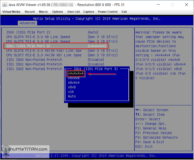
As mentioned before the motherboard should be compatible and BIOS should also have an option to enable it. You would need to dig the bifurcation options for your motherboard in BIOS settings, for Supermicro X10SRH-CLN4F (BIOS v3.2 Build 11/22/2019) the settings are located below:
BIOS -> Advanced -> Chipset Configuration -> North Bridge -> IIO Configuration -> II01 Configuration:
Optimal PCIe Bifurcation Configuration – Use case 1:
If the “Dual NVMe PCIe Adapter” is plugged into PCIe Slot4, “IOU1 (IIO1 PCIe Port 3)” config would need to be changed from “Auto” to “x4x4x4x4”, which will result in the PCIe v3.0 Link3 split/bifurcate into four(4) x4 chunks and the table will now look like:
| PCIe Slot Number | CPU/PCIe Port | PCIe version | PCIe Slot Size | PCIe Lanes |
| 2 | DMI2 | 2.0 | x8 | x4 |
| 3 | DMI2 | 2.0 | x4 | x2 |
| 4 | 3A | 3.0 | x8 | x4x4 |
| 5 | 2A | 3.0 | x8 | x4 |
| 6 | 2C | 3.0 | x16 | x8 |
| 7 | 3C | 3.0 | x8 | x4 |
Note: As I explained in the “Interpretation of motherboard layout and its architecture” section, the CPU/PCIe Link 3 has three(3) ports i.e. CPU/PCIe Port 3A, 3C and 3D. CPU/PCIe Port 3A is the only port that is affected with this config change, which now splits/bifurcates it from x8 to x4x4 and as a outcome will detect both the NVMe SSDs. The remaining CPU/PCIe Port 3C and 3D remain unaffected as they were already using x4 lanes.
Optimal PCIe Bifurcation Configuration – Use case 2:
If the “Dual NVMe PCIe Adapter” is plugged into PCIe slot5, “IOU1 (IIO1 PCIe Port 2)” config would need to be changed from “Auto” to “x4x4x4x4” instead, which will result in the PCIe v3.0 Link2 split into four(4) x4 chunks and the table will then look like this:
| PCIe Slot Number | CPU/PCIe Port | PCIe version | PCIe Slot Size | PCIe Lanes |
| 2 | DMI2 | 2.0 | x8 | x4 |
| 3 | DMI2 | 2.0 | x4 | x2 |
| 4 | 3A | 3.0 | x8 | x8 |
| 5 | 2A | 3.0 | x8 | x4x4 |
| 6 | 2C | 3.0 | x16 | x4x4 |
| 7 | 3C | 3.0 | x8 | x4 |
Optimal PCIe Bifurcation Configuration – Use case 3 (my use case):
If you have a GPU (which I do i.e. Nvidia 1080Ti installed in PCIe slot6) along with the multiple PCIe based NVMe SSDs, the optimal configuration to get peak performance from the PCIe slot6 i.e. all x8 lanes and successfully detecting two(2) NVMe SSDs in PCIe slot 5 would be, to change “IOU1 (IIO1 PCIe Port 2)” config from “Auto” to “x4x4x8” , and to detect another set of two(2) NVMe SSDs in PCIe slot4, “IOU1 (IIO1 PCIe Port 3)” would also need to be changed from “Auto” to “x4x4x4x4”. The table will now look like:
Peripherals
attached
I have plans to install three(3) more NVMe SSDs in the next couple of weeks i.e. two(2) x 1TB to replace my failed 2TB HDD and another 2TB for future prospects (possibly all three of 2TB sizes if there are any deals on the upcoming Amazon Prime Day this months ).
Hope this helps in making your purchase decision or helps understand your existing motherboard architecture’s and its PCIe bifurcation configurations.
Рассматриваем возможность подключения двух видеокарт к одному слоту — по видеоматериалам канала TechQuickie

Бифуркация. Это причудливое слово, которое означает разделить что-то на две части, и сегодня мы поговорим о раздвоении чего-то, что не является сандвичем, спортивным событием или браком. Этот пост посвящен бифуркации PCI Express слота.
 Это именно то, на что это похоже: взять слот PCI Express и поделить его, чтобы мы могли использовать несколько устройств. Но как это работает? Я имею в виду, вы не можете просто засунуть две видеокарты в один слот.
  Чтобы ответить, мы обратились к Филиппу Махеру из TYAN,
реклама
 и мы хотели бы поблагодарить его за его вклад. Нужно найти где и как настроены линии PCI Express на современных платформах. Ваш ЦП имеет определенное количество контроллеров, и каждый из них может поддерживать только одно устройство. Например, несмотря на то, что текущий процессор Intel поддерживает 16 линий, он разделен на четыре контроллера, управляющих четырьмя линиями в каждой, что означает, что вы можете подключить максимум четыре устройства PCI Express. Конечно, вы можете подключить одну видеокарту и использовать все 16 линий и закончить на этом.
  Но допустим, что вы хотите использовать несколько устройств хранения данных на PCI Express, например твердотельные накопители NVMe. Вот тут-то и нужна бифуркация. Видите ли, одно из наиболее распространенных применений бифуркации — это когда вы хотите подключить несколько дисков M.2 к одному слоту PCI Express. Это можно сделать с помощью необычной карты,
 которая выглядит примерно так, но вот загвоздка. Если вы собираетесь разделить только один слот, вам нужно указать материнской плате внутри BIOS, как именно разделить эти линии.
  В противном случае, он просто увидит одно из этих четырех устройств, и вы пожалеете, что потратили деньги. Как именно вы разделите эти дорожки, зависит от того, какую платформу вы используете. Как уже упоминалось ранее, частое что вы можете сделать на основной платформе Intel, — это четыре устройства по четыре полосы в каждом. Но на серверной платформе, такой как AMD EPYC, вы можете получить что-то около восьми устройств, хотя бы с двумя полосами на каждой, если вы используете так много устройств. Бифуркация встречается гораздо чаще в корпоративных условиях,
  поскольку центры обработки данных, как правило, используют линии PCE Express для вещей, которых вы просто не найдете дома, таких как
  ПЛИС и ИССН, микросхемы и устройства, которые можно настроить для работы над очень специфичными операциями. Но это не значит, что у бифуркации нет варианта использования раздвоения PCI Express для дома, к примеру при запуске двух видеокарт в одном слоте. Хотя для геймеров характерно использование только одной видеокарты на скорости x16, использование карты на x8 практически не повлияет на вашу производительность, поскольку даже современные высококачественные карты не перемещают достаточно данных, чтобы действительно нуждаться в этих дополнительных дорожках. Но, если у вас есть материнская плата с двумя свободными полноразмерными слотами PCI Express, дорожки автоматически разделяются переключателем, называемым мультиплексором, так что каждая карта работает на скорости x8.
  Но на самом деле ничто не мешает вам вставить карту с двумя слотами PCI Express x16,
  подключить две видеокарты с помощью переходных кабелей и попросить BIOS разделить слот на два соединения x8. Просто подумайте, что вы можете запустить NVLink на плате Mini-ITX с одним слотом, если вы найдете способ поместить карты в вашем корпусе, так что, надеюсь, вы не против использовать клейкую ленту.
  Но если вы заинтересованы в использовании раздвоения PCI Express, независимо от того, что именно вы будете подключать, вам необходимо убедиться, что ваша материнская плата и BIOS поддерживают его.
  Не все материнские платы позволяют включать его в BIOS, и если это так, то это в значительной степени ограничивает шоу. Так что проведите своё исследование, прежде чем принимать решение о превращении своей домашней установки в какой-то сумасшедший научный эксперимент.
Бифуркация (bifurcation) PCIe
Разделение (расщепление) порта PCI называют бифуркацией (bifurcation).
x1 PCI или одна линия PCI физически реализуется 4-проводным соединением (две дифференциальные пары).
Материнская плата содержит набор разъемов PCI на x4, x8, x16 и x32 линий. Процессор обменивается данными и посылает команды управления устройству, подключенному в порт (все линии PCI, объединенные в одном разъеме) одновременно по всем линиям асинхронно — то есть независимо друг от друга.
Если в один порт подключены несколько устройств, центральному процессору это надо объяснить, то есть — разделить, например, общую шину x16 на две по x8 или четыре по x4. В таком случае, ЦП точно знает — по каким линиям с каким из устройств он соединен.
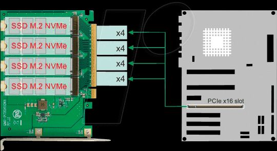
Управление бифуркацией каждого из портов PCI производится в BIOS, разделе Advanced (расширенный) / Chipset Configuration (конфигурация чипсета) / CPU Configuration (конфигурация ЦП). В двухпроцессорной системе — для каждого из портов каждого процессора.
Например, x16 порт может быть сконфигурирован как: x4x4x4x4, x4x4x8, x8x4x4, x8x8, x16, или Auto.
Бифуркация используется, в частности, при подключении адаптера с двумя NVMe SSD M.2 в PCIe порт.
[Motherboard] Compatibility of PCIE bifurcation between Hyper M.2 series Cards and Add-On Graphic Cards
Scan QR code to open this page with your smart phone.
[Motherboard] Compatibility of PCIE bifurcation between Hyper M.2 series Cards and Add-On Graphic Cards
Maximum M.2 SSDs support will vary depending on different CPUs.
Restrictions and Configurations for M.2 SSD installation
Restrictions
1. Update to latest BIOS before using RAID on CPU function.
2. For Z590, Z490, Z390 and Z370 series motherboard, install IRST version 16 or above to use RAID on CPU function. Only Intel SSDs can active Intel RAID on CPU function in Intel platform.
3. For X299 series motherboard, install VROC firmware to use VROC function. Only Intel SSDs can active Intel VROC function in Intel platform.
(Please refer to the 4th Q&A in below FAQ section to download the firmware)
4. For ROG STRIX Z590-I GAMING WIFI, be sure to use iGPU (Integrated Graphics Processing Unit) if you are going to use Hyper M.2 series card on your motherboard.
Configurations
Maximum M.2 SSDs support will vary depending on different CPUs and motherboards.Follow the instructions to install your M.2 SSDs.
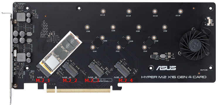
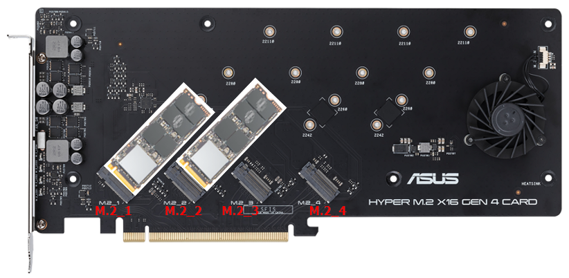
Three M.2 SSDs (Follow the image below to install SSDs if you are going to install only three SSDs on PCIe slot that can read up to four SSDs)
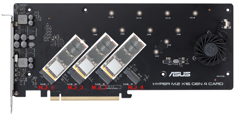
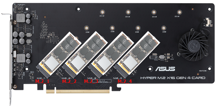
*Follow the steps below to install your M.2 SSDs if the PCIe slot of your motherboard can read only three M.2 SSDs on model list.
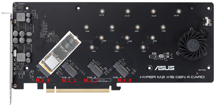
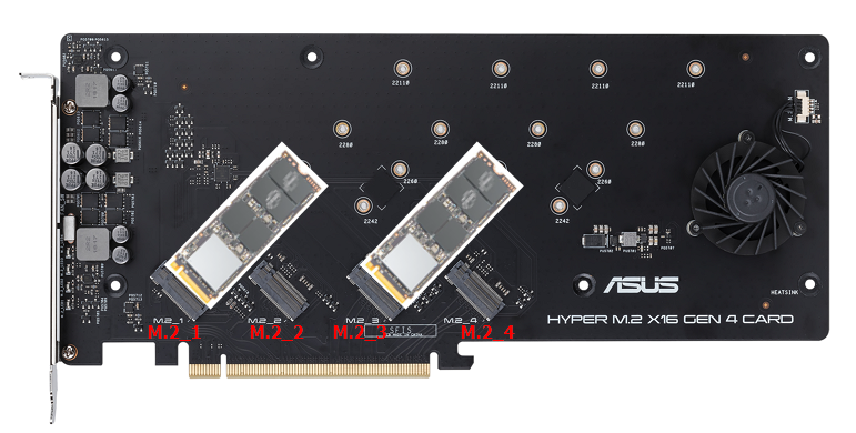
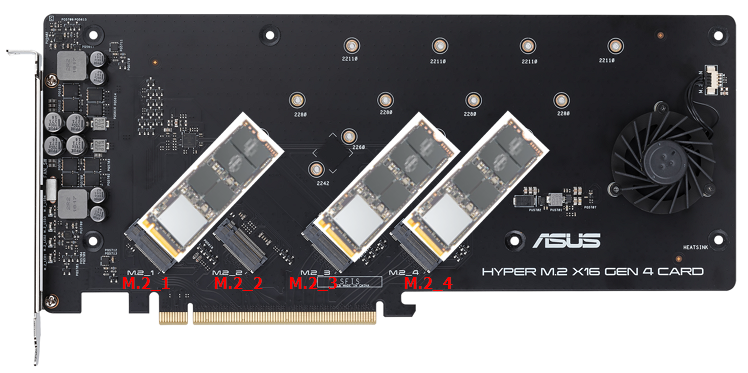
Inquire the quantity of M.2 SSD that motherboard will map when using Hyper M.2 Series Card.
Step 1. Find your motherboard name on model list. Take ROG RAMPAGE VI EXTREME OMEGA for example.

Step 2. Check the CPU that you use. For Intel series, please check PCI Express lane; For AMD series, please check the CPU model name.

Step 3. Check the PCIE slot that you are going to install the Add-On Graphic Cards. Example: 48-lane CPU, installing the add-on graphic card on PCIEX16_1.

Step 4. When installing four M.2 SSDs on PCIEX16_2, no more extra lanes to map M.2 SSDs on PCIEX16_3. When installing two M.2 SSDs on PCIEX16_2, extra lanes available to map two M.2 SSDs on PCIEX16_3.